LORD Corporation
With more than 3,100 employees in 26 countries, 19 manufacturing facilities and 10 R&D centers worldwide, we're there for our customers.
Our Company
-
Products and Solutions
To speak to someone directly, call
Customer Support:
8AM–5PM EST
Technical Support:
8AM–5PM EST
-
Industries
To speak to someone directly, call
Customer Support:
8AM–5PM EST
Technical Support:
8AM–5PM EST
-
Our Company
To speak to someone directly, call
Customer Support:
8AM–5PM EST
Technical Support:
8AM–5PM EST
-
Feedback Button
Feedback Button
Theory
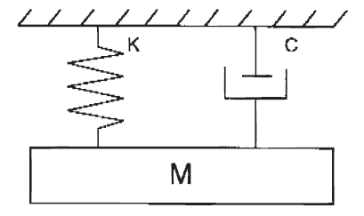
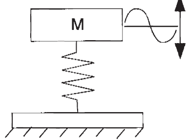
Vibration is an oscillatory motion. Any body with mass and elasticity can vibrate. The simplest type of vibrating system is called a single-degree-of-freedom spring-mass system. The spring is characterized by its spring rate, K, and a mass, M.
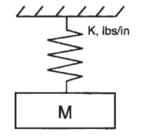
This system is called a single-degree-of-freedom system because motion can occur in only one direction. Spring rate defines the force required to induce a unit deflection of a spring. A steel spring has a linear relationship between force and deflection. Elastomeric springs may or may not be linear depending on the amount and direction of the load. Nonlinearity can be designed into elastomeric springs to achieve certain results. Elastomeric springs also differ from steel springs in that their stiffness is sensitive to the rate or speed of deflection. If a rubber spring is deflected quickly, it appears stiffer than if it is deflected slowly.
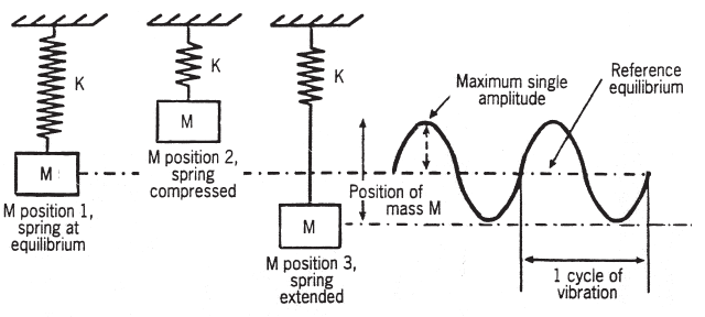
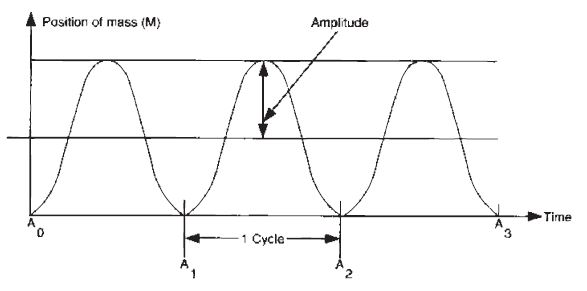
When a mass is attached to a spring, the mass moves to its position of equilibrium, position 1. The difference between the spring’s undeflected or free length and its position of equilibrium is called the system’s static deflection, ds. If a force is applied to the system, position 2, and then removed, the spring-mass system will vibrate, position 3. When plotted against time, the position of the mass relative to its equilibrium position is a sinusoidal curve. The maximum single amplitude is the deflection of the mass from its equilibrium position to its maximum displacement in one direction. Double amplitude displacement is the total deflection in both directions. The period of vibration is the time it takes for the mass to move from its equilibrium position to its peak in one direction, to its peak in the other and back to its equilibrium position.
If a load is applied to our spring mass system and then released, the mass will vibrate at a constant rate. We call this condition resonance, and the vibration rate is called the natural or resonant frequency. The natural frequency of a system can be considered a function of mass (M) and spring rate (K).
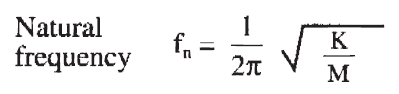
Natural frequency is usually measured in hertz. This equation can be written in many forms:
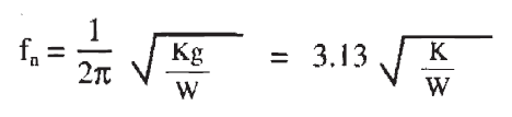
Where K=spring rate, lb/in; W=weight in pounds; M=mass in lb-sec2/in; and g=acceleration of gravity, 386.2 in/sec2. From this formula, you can see that an increase in mounting system stiffness or a decrease in weight will increase the natural frequency. A decrease in mounting system stiffness or an increase in weight will decrease the natural frequency. So far we have discussed free vibration, what happens when a force is applied and removed from our spring mass system. When a force is applied to the system as a sinusoidal vibration, the output through the system can be defined in terms of transmissibility. Transmissibility is the ratio of output to input and is dimensionless. Vibration output and input can be measured as motion, force, velocity or acceleration. The transmissibility of a mount is a function of the relationship of the input frequency to the natural frequency and the amount of damping.
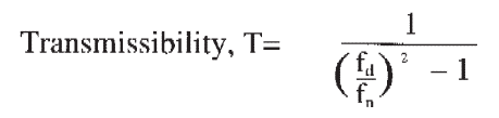
For undamped springs when fd/fn ≥ √2 where fd = input or disturbing frequency and fn= natural frequency.
In Figure 1, we see transmissibility plotted against the frequency ratio, fd/fn. When the disturbing frequency is very low compared to the natural frequency, the transmissibility is close to one, position 1. If the disturbing frequency is close to the natural frequency, the transmissibility is very high. The output is much larger than the input. (See Region of Amplification, position 2.) Position 3 is the crossover point when the fd/fn ratio is equal to the √2. When the disturbing frequency is high compared to the natural frequency, transmissibility is low. (See Region of Isolation, position 4.) Isolation is the goal of an elastomeric spring. We wish to attenuate a known disturbing frequency. From the desired transmissibility, we can define the required frequency ratio and calculate the system natural frequency. Using the natural frequency calculations, we can calculate the required spring rates for the vibration mounts. An elastomeric spring has another characteristic that a simple steel spring does not. It has hysteresis damping, C.
When an elastomeric mount is deflected, some energy is converted to heat. Without damping, a spring mass system will continue to oscillate at its resonant frequency for an extended time after the input has stopped. With damping, the oscillations decay more quickly. Damping also has an effect on transmissibility.
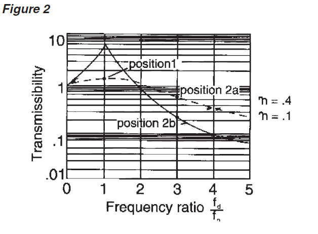
Figure 2 is a plot of transmissibility for two levels of damping, η. As you can see, the greater the amount of damping, the lower the transmissibility at resonance, position 1. Positions 2a and 2b have different transmissibility values for the same frequency ratio when using different values for damping. This illustrates the compromise an engineer must make when choosing the necessary amount of damping in an elastomeric vibration isolation mount. If the disturbing frequencies are known, we would design a lightly damped mounting system with a natural frequency well below the disturbing frequency. The low damping would provide optimum isolation. In cases where the disturbing frequencies are numerous, unknown or impossible to avoid, a highly damped system is preferred. The high damping reduces the peak response that can occur if the same disturbances are near the natural frequency of the mounts. A reduction in isolation efficiency will also occur. Vibration isolation employs resilient mountings and mounting systems to reduce the transmission of vibration from one point to another. All simple or single-degree-of freedom problems can be classified into two groups:
- Mass excited system: Protecting the supporting structure from vibratory disturbances originating in the supported mass.
- Base Excited System: Protecting the supported mass from the vibratory disturbances of the supporting structure.

In the first case, mass excited, the mass moves because of the vibrating force. This causes a deflection across the spring which transmits a force to the structure. This force must be reduced. In the second case, base excited, the vibrating or moving structure causes a deflection across the spring which transmits a force to the supported mass. This causes the mass to move. This motion must be reduced. When do you start thinking about vibration control? The earlier the better. The record proves that the best time to consider the need for vibration control is in the beginning stages of product design. The reward for this kind of foresight is best performance at the lowest cost. Your best chance of gaining this benefit comes when you call in a specialist as soon as the vibration or shock problem is recognized. Recognizing such a problem is a design responsibility. Vibration analysis is a requisite of equal importance with stress analysis, cost analysis, material selection and reliability assurance. No design is complete without all of these. These benefits are produced when the mounting system design coincides with product design:
• Accurate analysis of the dynamic environment.
• Precise determination of mounting system requirements.
• Most advantageous system configuration.
• Adequate space for mountings and sway space clearance for the mounted assembly.
• Predictable results through application of proven principles to meet exact requirements.
These are just a few of the reasons for considering vibration isolation early in design. It is apparent that the designer has everything to gain and nothing to lose by following this practice.
Shock Mechanics
Shock is a common phenomenon with many familiar sources: aircraft landings, impacting of railroad cars, power surges or impacts in marine drive systems, driving over bumps, dropping product containers, explosions, missile launching and staging. Thus, shock protection is a common requirement in good product design. Today’s trend to higher speeds, heavier loads, larger power plants and lighter weights accentuate the problem. Mechanical shock is a nonperiodic disturbance of a mechanical system characterized by suddenness and severity. Such extreme disturbances cause significant forces in the system which may be damaging. A shock input is non-repetitive in nature and of limited time duration. The response it produces normally decays to an arbitrarily small value before the next disturbance.
Shock inputs may be caused by:
1. A sudden introduction of energy into the system or a change in the level of energy in the system.
2. A force excitation.
3. An abrupt motion, velocity or acceleration change.
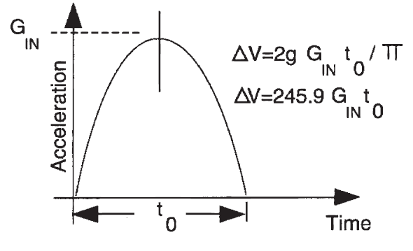
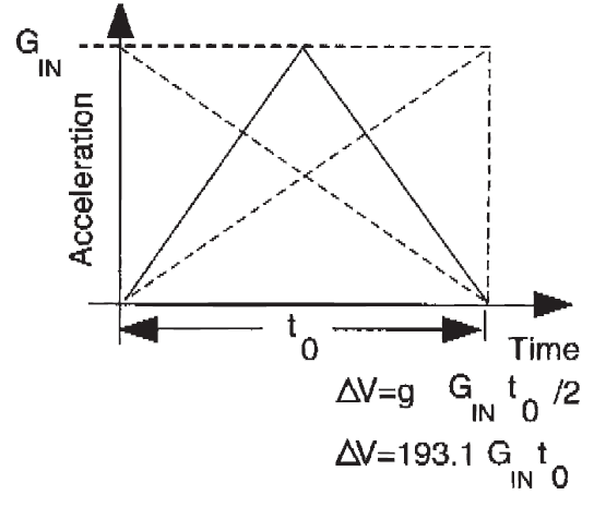
Analysis of a shock problem usually starts with an examination of the shock input. Shock inputs are of short duration and non-periodic. Often these short duration transient loads have complex wave shapes. Analysis may be simplified by comparing the actual wave shape to several simple wave shapes for which the response is known. Important features of the shock pulse are: maximum amplitude, time duration and approximate shape. The majority of excitations typically encountered are:
• Half-sine Shock Pulse
• Triangular Shock Pulse
• Drop Shock
• Velocity Shock
Each can be defined as:
• Half-sine Shock Pulse
• Triangular Shock Pulse
• Drop Shock

• Velocity Shock
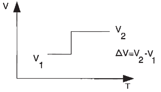
Where:
∆V = change in velocity, in/sec
g = acceleration due to gravity, 386 in/sec2
Gin = shock pulse magnitude, G’s
π = 3.1416
to = shock pulse duration in seconds
h = drop height in inches
V2 = velocity at point 2
V1 = velocity at point 1
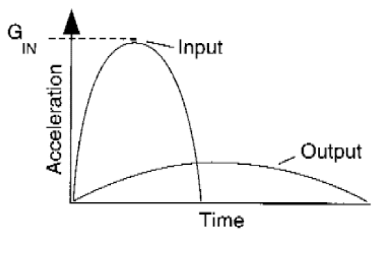
Engineers should consider mechanical shock by comparing the fragility level of the most sensitive component to the actual shock acceleration input. Fragility is defined as the highest acceleration level beyond which equipment will fail to operate within specification. The shock mount shall not permit the output acceleration to exceed the fragility level. The G’s output can be calculated by:
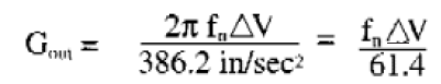
In other words, the input acceleration is absorbed by the resilient mount, and the shock energy is released over a broader time base. By dispersing the shock energy over a broader time base, the output accelerations are reduced.
The elastomeric vibration isolator must have the ability to accommodate the higher deflections that are characteristic of mechanical shock. The dynamic deflection, dd, can be calculated by:
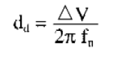
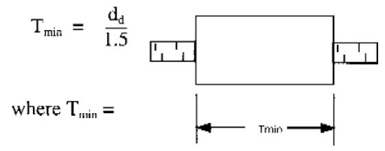
This dynamic deflection must not exceed the safe limits of the vibration isolator’s strain capability. We can use an equation to determine the minimum rubber wall thickness for a shear or sandwich vibration isolation mount:
The designer must also accommodate sway space within the product design. If not, even though the shock mount may be very efficient, lack of necessary sway space may cause secondary collisions resulting in the same damaging effect as if no shock attenuation devices were used.
If the concepts outlined above are kept firmly in mind, the designer will be well on his way to the most efficient attenuation of shock in a wide variety of applications.
Elastomers for Vibration Isolation
“Rubber” is a synthetic or natural material whose long-coiled, high molecular weight chains have been cross bridged by certain chemical ingredients to form a network. It is characterized by the ability to accept and recover from extreme deformation of 200% or more. The term “elastomer” includes natural rubber and the many synthetic materials that possess rubber-like properties. Choice of an elastomer invariably hinges on the balance of properties offered. Some properties are interdependent, and the designer should understand the effect of one upon the other. To gain a desirable characteristic, for example, it may be necessary to accept reduction in some other property. Two or more optimum properties may be obtainable together. Within the various families of LORD vibration isolation products, a number of elastomers may be selected. Some brief description may help guide in their selection for a particular problem.
Selection and Service Guide for Elastomers
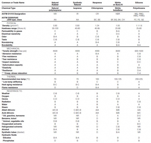
A = Excellent B = Good C = Fair D = Poor NR = Not Recommended
- The higher the density, the more rubber is required to make a given part. For example, compare neoprene and natural rubber. Even at the same price per pound, neoprene would be more expensive to use.
- While tensile strength per se is not necessarily important, retention of strength at elevated temperatures suggests retention of other mechanical properties as well.
- Abrasion-resistance ratings apply to a wide range of temperatures as well as type of abrasion (such as rubbing and impingement).
- A high resistance to crack-growth indicates good general durability – necessary where physical abuse is expected.
- Tear resistance, along with crack-grown resistance, is desirable where physical abuse is expected.
- Rubbers that strain-crystallize at extreme deformations are much more durable in impact than those that do not. Low-temperature flexibility also helps improve impact performance.
- A high deformation capacity usually indicates a high fatigue resistance to flexing.
- The lower the permanent set, the better the structural integrity and the better the retention of initial dimensions.
- The higher the resistance, the less the degradative heat buildup in a flexing or dynamic situation.
- The better the resistance to creep, the longer the life of the part, particularly where clearances are to be maintained.
- Resistance to stress relaxation is essential in seals and other components under steady stress in service.
- Good low-temperature flexibility is a must for most shock absorbers. The first jolt is critical, regardless of subsequent softness.
- Resistance to oils and greases is essentially a surface effect: parts with poor resistance to these substances but that have appreciable bulk will not be degraded by such exposure.
Terms and Definitions
There are a number of terms which should be understood before entering into a discussion of vibration and shock theory. Some of these are quite basic and may be familiar to the users of this catalog. However, a common understanding should exist for maximum effectiveness.
Acceleration – rate of change of velocity with time. Usually along a specified axis, usually expressed in “G” or gravitational units. It may refer to angular motion.
Amplitude – the maximum displacement from its zero value position.
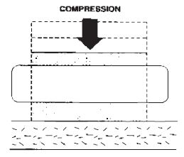
Compression – when specified as a direction for loading – a deformation caused by squeezing the layers of an object in a direction perpendicular to the layers.
Damping (c) – the mechanism in an isolation system which dissipates a significant amount of energy. This mechanism is important in controlling resonance in vibratory systems.
Disturbing Frequency (fd) – the number of oscillations per unit time of an external force or displacement applied to a vibrating system. fd = disturbing frequency.
Durometer (hardness) – an arbitrary numerical value, which measures the resistance to the penetration of the durometer meter indenter point; value may be taken immediately or after a very short specified time.
Fragility – is the highest vibration or shock level that can be withstood without equipment failure.
“G” Level – an expression of the vibration shock acceleration level being imposed on a piece of equipment as a dimensionless factor times the acceleration due to gravity.
Isolation – the protection of equipment from vibration and/or shock. The degree (or percentage) of isolation necessary is a function of the fragility of the equipment.
Load Deflection Curve – the measured and recorded displacement of a mounting plotted versus an applied load.
Natural Frequency (fn) – the number of cycles (expressed as Hertz or cycles per second) at which a structure will oscillate if disturbed by some force and allowed to come to rest without any further outside influence.
Random Vibration – non-sinusoidal vibration characterized by the excitation of a broad band of frequencies at random levels simultaneously.
Resonance – vibratory system is said to be operating at resonance when the frequency of the disturbance (vibration or shock) coincides with the system natural frequency.
Set –the amount of deformation never recovered after removal of a load. It may be in shear or compression.
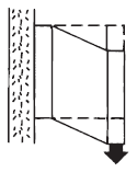
Shear – when specified as a direction for loading – a deformation caused by sliding layers of an object past each other in a direction parallel to the layers.
Shock Pulse – a shock pulse is a transmission of kinetic energy to a system, which takes place in a relatively short length of time compared to the natural period of this system. It is followed by a natural decay of the oscillatory motion. Shock pulses are usually displayed as plots of acceleration vs. period of time.
Spring Rate –the force required to induce a unit deflection of spring. A steel spring has a very linear relationship between force and deflection. Elastomeric springs may or may not be linear depending on the amount of deflection due to the load.
Static Deflection (ds) – the deflection of the isolator under the static or deadweight load of the mounted equipment.
Transmissibility (T) – is a dimensionless unit expressing the ratio of the response vibration output to the input condition. It may be measured as motion, force, velocity or acceleration.
Videos