LORD Corporation
With more than 3,100 employees in 26 countries, 19 manufacturing facilities and 10 R&D centers worldwide, we're there for our customers.
Our Company
-
Products and Solutions
To speak to someone directly, call
Customer Support:
8AM–5PM EST
Technical Support:
8AM–5PM EST
-
Industries
To speak to someone directly, call
Customer Support:
8AM–5PM EST
Technical Support:
8AM–5PM EST
-
Our Company
To speak to someone directly, call
Customer Support:
8AM–5PM EST
Technical Support:
8AM–5PM EST
-
Feedback Button
Feedback Button
Dynafocal® General Aviation Engine Mounts Where to Buy
LORD set the standard for elastomeric engine mounts more than 70 years ago by providing the first Dynafocal engine mounts for aircraft. Today, LORD mounts continue to provide superior performance and life at all levels of General Aviation. Millions of LORD mounts have been produced, sold into the market place and flown by operators all over the world. With best-in-class quality and performance, most major OEMs and service shops specify LORD mounts.
LORD engine mounts are available for many aircraft, including the most produced general aviation aircraft models, such as the Cessna 152, Cessna 172, Cessna 182, Piper PA-28 series, and many more – please see our brochure below for a full listing. Because of our strong history of vibration and motion control products, we offer a wide array of innovative solutions for the aerospace industry. We can work with you to determine the LORD mount for your aircraft.
DOCUMENTS
General Aviation Products Brochure
Application Guide/Engine Mount Selector
LORD vs. The Competition | LORD vs. Barry Engine Mounts | LORD vs. VIP Mounts
LORD Engine Mounts for general aviation have key design characteristics and features that competitive mounts simply don’t. When selecting your next set of engine mounts, don’t just take our word for it, read what other general aviation aircraft owner/operators are saying about LORD Mounts or watch them in action!
Maintenance of GA Engine Mounts
For type certificated aircraft, you must use the FAA approved component maintenance manual.
Bonded sandwich assemblies are natural rubber or specially blended synthetic compounds bonded to two plates. The normal installation requires four assemblies, each consisting of two sandwich mountings and one spacer. Satisfactory performance requires that the spacer be designed to the correct length to precompress each mounting to guarantee proper positioning of the mountings. When properly installed, these mountings provide excellent isolation of engine vibration, resulting in smoother, quieter flight. Always order replacement mountings by the mounting assembly number to ensure the correct spacer.
At each annual inspection and at FAA-required inspections of the aircraft’s engines, all mounting assemblies should be visually inspected in their installed state while supporting the engine weight. The correct visual inspection procedure is as follows:
To remove mounting assemblies from the installation, it is necessary to remove the engine weight from the mountings, by the use of a chain hoist or equivalent, and disconnect the nuts and bolts which hold the mountings in place. In general, removal of one mounting at a time can usually be accomplished, if necessary, without removing the engine weight from the mountings.
- General Comments
-
Visual Inspection of Installed Mountings
CAUTION: WHENEVER THE AIRCRAFT’S ENGINES ARE CLEANED DURING A NORMAL INSPECTION, COVER EACH MOUNTING ASSEMBLY TO PROTECT IT FROM CONTAMINATION BY CLEANING FLUIDS OR SOLVENTS. THIS ALSO APPLIES TO ENGINE LUBRICANTS. SHOULD ANY SUCH MATERIALS ACCIDENTALLY GET ON A MOUNTING ASSEMBLY, WIPE IT OFF THOROUGHLY AS SOON AS POSSIBLE WITH A CLEAN, DRY RAG.
- Inspect all bonded sandwich mountings for metal-to-rubber bond separations, flex cracks, rubber deterioration due to exposure to fluids, and mechanical damage such as cuts in the rubber surface.
- Visually inspect all bonded steel parts for cracks and excessive nicks, scratches or gouges.
- Inspect all nut locking wires for looseness and tighten as necessary.
- When applicable, measure all drift indicators in each mounting assembly for excessive deflection.
- Whenever any of the conditions detailed above in steps a, b and d are found, remove the mounting assembly from the engine, disassemble, inspect and repair it as described in the maintenance manual.
- Disassembly
-
Cleaning & Inspection
- Wipe oil and dirt from bonded mountings, but do not dip in cleaning solvents.
- Steel bolts and spacers should be inspected for cracks or damaged threads. Examine spacers for crushing of ends, caused by excessive tightening torque on bolt. Replace if either condition is apparent.
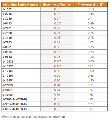
- Examine bonded rubber mounting for oil swelling, bond or rubber separation and shear or compression set. Bond separation, oil swelling or flex cracks in the surface of the rubber are cause for rejection. The effects of shear and compression set are determined by measuring the dimensions shown on the sketch. Reject parts which have an eccentricity greater than dimension “A” or an overall thickness less than dimension “B”.


